Design
Tips Newsletter
Fun with Fonts!
Edition 2
March 2012
This month Design Tips focuses on fonts and the innovative things you can do with fonts from within Cutting Shop. Once you have mastered a few Cutting Shop basics you can quickly knock out professional grade signage in just a few minutes.
Since Cutting Shop’s basic font outlining seems to be easily understood by everyone, or at least everyone who has glanced at the manual, we won’t go into that now.
There are two font tools, the “A” tool and the Curve Text tool; they both let you choose among any TrueType font on your system, you can size the font in decimal or metric units and change the relative character angle. Also, they both outline the font with “Polylines.”
Curve text additionally places text on what ever polyline you have selected, which is a line with black dots at each end. Remember that Cutting Shop’s Polylines consist of long lines and arcs and are designed so that editing is a snap.
Because text tools create polylines, and use Optimize (see Design Tips 1, Optimize) you should have Show Points on (F2); otherwise it is difficult to determine if the result is as good as it can be. It is also necessary when using Curve Text so that you can determine exactly where your text will flow.
 The
Text tool
The
Text tool
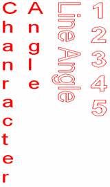
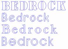
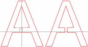
The examples on the left were created with the Text Tool. “Character Angle” was written with “Angle” on the first line and “Character” on the next line. Character Angle was set to 90 and Text Line Angle set to 270; this has not been “Converted to Polylines,” so it is still a font.
“Line Angle” was set to 270 and “Relative Character Angle” was 0. This was “Converted to Polylines” and is made of lines and arcs in a polyline format.
The vertical numbers are a typical design with address numbers.
 We’ve
had a lot of questions regarding Cutting Shop “Stroke Fonts.” Stroke fonts are optional; there are several
fonts available. These fonts work with both the Text tool and the Curve Text
tool. Cutting Shop Stroke fonts do not work within other programs. We have centerline stroke fonts and outline
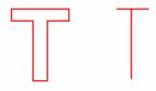
stroke fonts. For example, outlining the
simplest letter T in a TrueType form requires a total of 8 lines. Whereas the simplest T in a Stroke font is 2
lines, the down stroke and the cross bar.
These are typically used when marking parts. There are 4 centerline
Stroke fonts available. Like TrueType
fonts, Stoke fonts must also be “Converted to Polylines” so that they can be
cut.
We’ve
had a lot of questions regarding Cutting Shop “Stroke Fonts.” Stroke fonts are optional; there are several
fonts available. These fonts work with both the Text tool and the Curve Text
tool. Cutting Shop Stroke fonts do not work within other programs. We have centerline stroke fonts and outline
stroke fonts. For example, outlining the
simplest letter T in a TrueType form requires a total of 8 lines. Whereas the simplest T in a Stroke font is 2
lines, the down stroke and the cross bar.
These are typically used when marking parts. There are 4 centerline
Stroke fonts available. Like TrueType
fonts, Stoke fonts must also be “Converted to Polylines” so that they can be
cut.
 There
are also 4 outline stroke fonts available. These are pre-bridged fonts and are
used in stenciling situations. Of course with the Bridge Tool you can always
create a stencil type text with any TrueType font that has been “Converted to
Polylines.”
There
are also 4 outline stroke fonts available. These are pre-bridged fonts and are
used in stenciling situations. Of course with the Bridge Tool you can always
create a stencil type text with any TrueType font that has been “Converted to
Polylines.”
 The Curve Text tool
Curve Text follows a pre-drawn curve. The curve is a polyline which can be made of a series of lines and arcs. The start and stop positions of the Polyline should each have a black point (f2). To put text on circle first use the Con P/L tool to convert the circle into two arcs. Use the Insert Point tool to insert the starting and ending points of the polyline you want to follow. Then use the Cleave tool on each of the new points; it defines a polyline.
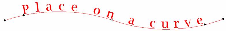
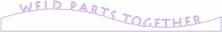
In the above example the polyline was selected and the font followed the curve. However the font is just above the line. In the following example the font was lowered so that the bottoms of the individual letters were just below the curve. With the letters touching a closed polygon it is a simple step to Weld the letters so that there is a continuous line running around the part.
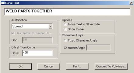 The
Curve Text dialogue on the right is used to insert text on a polyline and is where
you lower your font onto the polyline. Enter a negative value into “Offset from
Curve” to lower the font. This value can
be measured with the Draw tool. Zoom into an area that includes both the curve
and the bottom of a letter. With the Draw tool active, click near the bottom of
the letter then move the curser to the line but don’t click. Now read the value at the bottom left box at
the bottom of the screen. This is an approximate value and is accurate enough
to get a value that you can work with. Fill Right click to cancel drawing the line. Fill in the Offset value and click OK.
The
Curve Text dialogue on the right is used to insert text on a polyline and is where
you lower your font onto the polyline. Enter a negative value into “Offset from
Curve” to lower the font. This value can
be measured with the Draw tool. Zoom into an area that includes both the curve
and the bottom of a letter. With the Draw tool active, click near the bottom of
the letter then move the curser to the line but don’t click. Now read the value at the bottom left box at
the bottom of the screen. This is an approximate value and is accurate enough
to get a value that you can work with. Fill Right click to cancel drawing the line. Fill in the Offset value and click OK.
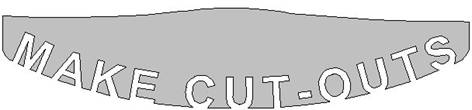 We
occasionally get queries about placing text on the bottom line in a polyline with
the text on the inside of the polygon.
This is a good question, because if after placing your text where you
want it and converting to polylines, the next step would normally be to weld. However this does not work with text inside a
polygon; the text disappears leaving behind points on the polyline. So, instead of using the Weld tool; Select
All (Ctrl A) then from the drop down menu at the top of the screen choose Edit/Break at
intersections. Show Points (F2) should be on. Break at intersections puts a point at the
position where two lines cross. The
lines you don’t want are then easily deleted with the Delete tool, or Selected
with the Select tool and then deleted, with the Delete key on your keyboard.
When done Uncleave to ensure all your lines are closed. In the
this example a gray solid fill was used to hi-light the parts. Notice that pieces of the M, A, K and O will
fall out. Check out the Bridge tool.
We
occasionally get queries about placing text on the bottom line in a polyline with
the text on the inside of the polygon.
This is a good question, because if after placing your text where you
want it and converting to polylines, the next step would normally be to weld. However this does not work with text inside a
polygon; the text disappears leaving behind points on the polyline. So, instead of using the Weld tool; Select
All (Ctrl A) then from the drop down menu at the top of the screen choose Edit/Break at
intersections. Show Points (F2) should be on. Break at intersections puts a point at the
position where two lines cross. The
lines you don’t want are then easily deleted with the Delete tool, or Selected
with the Select tool and then deleted, with the Delete key on your keyboard.
When done Uncleave to ensure all your lines are closed. In the
this example a gray solid fill was used to hi-light the parts. Notice that pieces of the M, A, K and O will
fall out. Check out the Bridge tool.
Spacing between letters
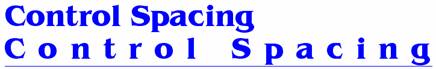 The
Text tool makes letters with uniform spacing. If you need to control the
spacing between letters use the Curve text tool. Just draw a line the length
that you need for your letters and then with the Curve Text tool click on the
line and type your message. Use “Spread”
justification so that the letters are spread over the entire length of the
line.
The
Text tool makes letters with uniform spacing. If you need to control the
spacing between letters use the Curve text tool. Just draw a line the length
that you need for your letters and then with the Curve Text tool click on the
line and type your message. Use “Spread”
justification so that the letters are spread over the entire length of the
line.
 The Bridge tool
 Bridging
is used to keep parts from falling out. First you’ll need to know how large to
make the bridge. If you don’t know what the size should be, try measuring with
the Draw tool. The thickness of a leg of a letter or half the thickness of the
leg might be what you need. With the Bridge tool active, double left click to
get the Bridge dialogue box. Change the bridge size and click on a line that
you want to be bridged; the line you picked will become dashed, tool guides
will appear as black dashed lines, the guides show where your bridge will be.
If you don’t see any guides, you have not clicked on a line, or your bridge is
larger than the area you are bridging. If the bridge guides are where you want
it to be then click on the second line and the bridge forms.
Bridging
is used to keep parts from falling out. First you’ll need to know how large to
make the bridge. If you don’t know what the size should be, try measuring with
the Draw tool. The thickness of a leg of a letter or half the thickness of the
leg might be what you need. With the Bridge tool active, double left click to
get the Bridge dialogue box. Change the bridge size and click on a line that
you want to be bridged; the line you picked will become dashed, tool guides
will appear as black dashed lines, the guides show where your bridge will be.
If you don’t see any guides, you have not clicked on a line, or your bridge is
larger than the area you are bridging. If the bridge guides are where you want
it to be then click on the second line and the bridge forms.

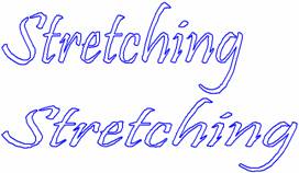
The Stretch tool
Stretch is another option when dressing up your drawing. When using Stretch be sure that Show Points (F2) is on. Stretching tends to put additional points on elements that are being stretched. You might want to use the Optimize tool to reduce node points.

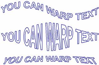
The Warp tool
The Warp tool is another tool that can help you make a sign pop. Warp has several pre-designed shapes. With the Warp tool active double-left click to view your shapes, then draw a box around the parts that you want to be warped. Repeating the process increases the amount of warp, or you can apply different warps sequentially to produce new effects.